Equipment For Sale


.gif)


10135 Results Found
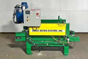
PRS MODEL T Pallet StackerSpecifications: -- Fixed 48x40 -- Hydraulic Lift and Chain Conveyance -- Fully Automatic -- Programmable Stack and Eject -- Factory Refurbished Fall 2022
$ 12,200

PANHANS - 436, ...24'' Single Surface Planer -- Specifications24.8" (630 mm) Width x 1/8" to 10" opening; 10 HP Motor; 4-knife - 4-3/4" dia. cutterhead belt driven @ 5,000 RPM; max. cutting depth: 5/16". -- 1 HP Feed motor with: (2) Feed speeds: 22 - 44 FPM. Segmented rubber-covered infeed and outfeed rollers, sectional chip breaker, motorized raise-and-lower of bed w/LED readout, table size 43" x 21". -- Options Include: (16) Cutter knives: Power lift up & down. -- Complete with: Emergency stop;, magnetic starter w/overload protection; knife setting gauge: & 5-1/2" dia. dust hood; includes: Operations manual; parts list; tool kit.
Call for Price

Model P30N 600 V / 3 Ph / 60 Hz Includes Transformer

Call for Price
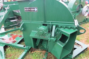
48" Beloit-Passavant Chipper

Call for Price
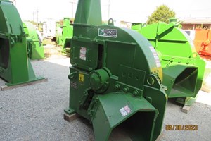
Passavant MDL 106.4-110D 3K Chipper S/N 504113
Call for Price

Call for Price
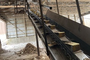
Patz 12" x 134' Barnsweep Bark Conveyor with 35' Double Sided Steel Chute and Electric Drive.
Call for Price
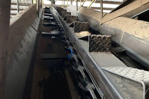
Patz 12"x36' Barnsweep Conveyor w/ 35' Double-sided Steel Chute w/ Electric drive (clockwise)

Call for Price

Call for Price
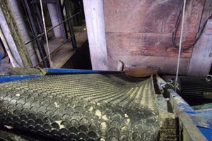
Patz 28" x 18' Approx. Belt Conveyor
Call for Price
Paul AB920 Rip Saw Scanning Fenceless Infeed Infeed & Outfeed (not including decks) The machine has one fixed and 2 moving blades. The minimum distance between the moving blades is 44 mm (1.73"). The maximum distance between the moving saw blades is 210 mm (8-1/4"). The machine is designed for incoming boards with the following min./max. dimensions Length: 4' - 16' Width: 2" - 19" Ripped widths: 1.75" - 8" Thickness: 1" - 2" 480 Volt, 60 hz., 3 phase electrics 75 HP main motor Automatic edging separation after the saw Feed speed up to 300 fpm Fenceless infeed system with automatic skewing capability 16 width sensors on the infeed system
Call for Price

PAUL K34V/1000 RIP SYSTEM WITH (1) SHIFTING BLADE39.3" (1000 mm) max. cutting width x 4.1" (105 mm) max. thickness cap. -- Specifications: Bottom arbor design; (6) powered bottom and (6) powered top feed rolls propel lumber from the infeed system thru the Ripsaw.50 HP (37 kW) Main motor, 2,900 RPM driving a 2.362" (60 mm) dia. arbor with (1) moveable blade. Moveable saw has a shift-able range of 400mm.Moveable blade and fixed fence positions indicated by 15mw laser lights that project 16' lines down inbound boards. Arbor is removable on a slide system; -- Feed Works: 49 - 262 FPM (15 - 80 MPM) Variable feed speed feed drive; hydraulic drive to (3) sets of smooth top and corrugated bottom feed rolls before and (3) sets of smooth top and corrugated bottom feed rolls after the blades and individually controlled pressure to the feed rollers. With (3) sets of anti-kickback fingers. -- Equipped with: Automatic oiler, push-button station, upper dust hood and upper and lower dust chutes. In-feed roller table 980 mm with (7) rollers; universal type mounted to the machine. -- Operator Interface: 1 NCD control, VGA color monitor, features 10-width lists with 200 items (8 variable-width lists, 2 set-up lists for long bush fitted for fixed blades.) -- Machine is under power but not in production.

$ 4,500

PAULSON 4 Head Through Feed MoulderSpecifications -- 4-heads (T-L-R-B) 6" x 2" moulder; -- 7-1/2 HP motor on the 1st top spindle, -- 7.5 HP motor on the left and right -- 7.5 HP motor on the bottom spindle.Equipped with & Features -- 3 HP variable speed feed works with feed speeds from 10 to 75 FPM. -- (2) top and (1) bottom powered feed rolls before the 1st top head --. All spindles are belted from the motors driving at 8,000 RPM are 1-1/4" dia. -- complete with 1/3 of the misc cutterheads shown in the photo. -- NOTE: (3) identical Moulders available. .
Call for Price
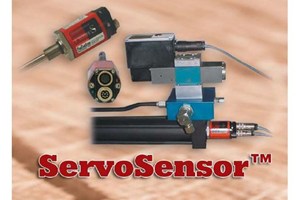
The S-Series ServoSensor™ is a complete servo controller installed and interfaced inside an MTS® R-Series platform. It consists of a Servo Controller Module (SCM), driver module (DM) and sensing element (SE) combined inside the sensor head body. MTS® proprietary technology is integrated directly to the SCM. This integration in the SCM provides the ServoSensor™ Controller with very fast displacement measurements and servo control outputs. Hydraulic cylinders can typically be positioned to .001"

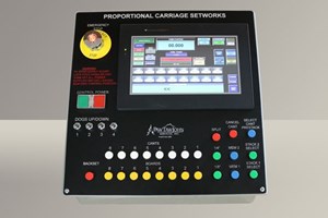
This is a robust design for longer operation and performance which means more uptime. This system was designed with ease of use and ease of installation in mind for all varieties of our customers. Call for more information.
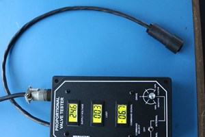
This is an in-line electrical monitor for proportional hydraulic valves with on-board electronics. Designed to monitor those voltages which can affect the control of proportional hydraulic valves in a hydraulic system. Please call for more information. TESTIMONIAL:I am the Operations Manager at GPM Hydraulic Consulting and we have been using the Model PVT-02 proportional valve tester to troubleshoot proportional valves for our customers for many years now. We have purchased test boxes for all of our Consultants to use in the field when troubleshooting. This test box has saved us hours of troubleshooting and in return saved our customers hours of downtime. The box is connected in a series so you can observe the supply voltage, command signal and LVDT (linear variable differential transformer) feedback from the proportional valve while the system is running normally. You can also use the box instead of the PLC to drive the valve to see if the problem is the controller or valve itself. If you have proportional valves, you need to get one of these test boxes. Without the box to troubleshoot, your valves may get changed when there is nothing wrong with them. This box is also very affordable, a lot cheaper than what a proportional valve costs. Last year I went on a consult for a company that made floor panels for BMW. A proportional valve is what controlled the press opening and closing but the press would not move. I connected the test box to their valve in series to watch the power supply, command and feed back voltages. When a command was given to lower the press, a power supply voltage of 22.6 volts was supplied to drive the valve amplifier. Normally the voltage should be 24 volts however, 22.6 was within the acceptable limits of operating the amplifier. The command voltage applied was 3.5 volts. The LVDT feedback voltage should have been 3.5 however, it was reading near 0 at .4 volts. This indicated that the main spool did not move. We then move the selector switch to drive the valve with the box. The voltage was increased to 10-volt manually. The LVDT feedback continued to read .4 volts indicating that the pilot valve shifted but the main spool did not. We removed the valve assembly and found that contamination had caused the spool to stick.

Call for Price

Call for Price

(2) 14 Unit Peerless Chip Bins Down and Ready to ship.
Call for Price

Peerless 21 unit chip bin, ready to load
Call for Price

Peerless 21 unit chip bin, ready to load